
Can A Circuit Board Be Fixed? | Complete Beginner’s Guide To Technicians (2025)
Circuit boards, also officially referred to as Printed Circuit Boards (PCBs), are employed in every electronic gadget — from mobile phones and televisions to computers, industrial control panels, and medical devices.
Though critical, a faulty circuit board can render extreme functionality problems. But the good news: most circuit boards are repairable, if the damage isn’t too widespread.
Through this in-depth guide, we will discuss:
- Can circuit boards be repaired
- What tools are required
- Step-by-step repair process
- Error prevention
- Professional guidance and prevention methods
Is a Circuit Board Repairable?
Yes, it is often possible to repair a circuit board, but it is determined by the type and severity of damage.
Common Types of Repairable PCB Damage:
- Burned or Marred Components: Resistors, capacitors, and ICs are replaceable.
- Bridged PCB Traces: Copper traces between components can become bridged or rerouted.
- Loose Pads: A loose solder pad can usually be fixed or bypassed.
- Broken Solder Joints: Cold or cracked joints can be refilled to fix them.
- Water Damage or Corrosion: Water-damaged boards can usually be revived after drying out and cleaning.
Hard-to-Repair Situations:
- Extensively burned multilayer PCBs
- Internal layers damaged (on 4+ layer boards)
- PCB with proprietary or encapsulated components
- No-replacement custom ASICs. Typically, consumer electronics, DIY equipment, and industrial boards are repairable, while new smartphones or tablets are not economical to repair due to miniaturization and board complexity.
How To Repair A Circuit Board (Preparation)
Prior to initiating any repair, gather required tools and prepare a clean, static-free working area.
Tools and Materials Needed
- Soldering iron (temperature-controlled, 30W–60W)
- Desoldering tools (solder wick/braid, desoldering pump)
- Leaded or lead-free solder
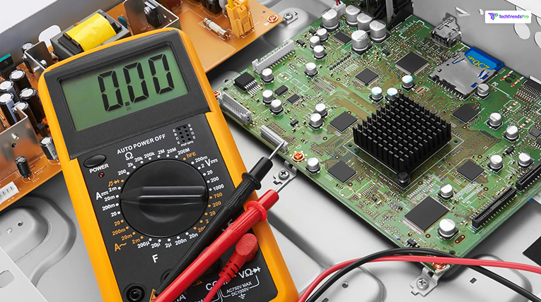
- Multimeter (voltage, resistance, continuity tests)
- Isopropyl alcohol (preferably 99% grade)
- ESD-safe tweezers
- Flux pen or paste
- Fine-gauge jumper wires (30 AWG, etc.)
- Magnifying glass or microscope
- Small brush
- PCB holder or clamp
- Hot air rework station (SMD components)
- Replacement parts (ICs, resistors, capacitors, etc.)
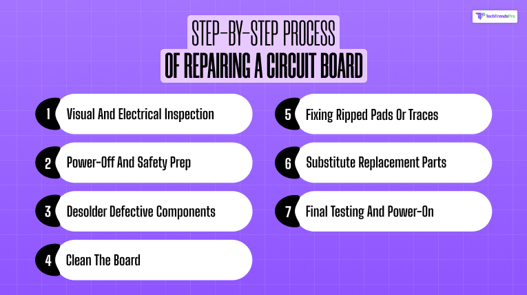
Step-by-Step Process Of Repairing A Circuit Board
Here are the steps that you need to follow in order to repair a circuit board.
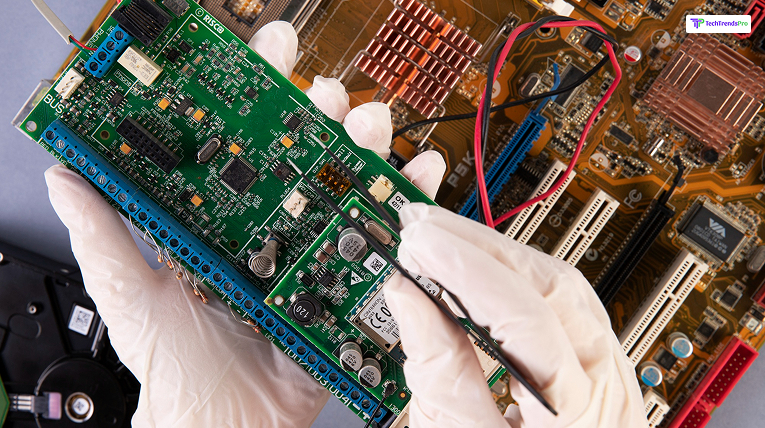
Step 1: Visual And Electrical Inspection
Begin by visually inspecting the board:
- Look for burn marks, bulging or leaking capacitors, loose connections, or colored areas.
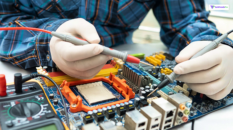
- Employ a multimeter to test trace continuity, probe power rails, and locate shorts.
- Advanced Tip: Employ a thermal camera or infrared thermometer to locate overheating components when powered.
Step 2: Power-Off And Safety Prep
- Unplug the device and drain the capacitors.
- Wear an ESD wrist strap to prevent electrostatically destroying sensitive chips. ⚡ Some power capacitors hold a charge even when disconnected. Double-check with a multimeter in all instances.
Step 3: Desolder Defective Components
- Replace the joints with heat using your soldering iron or hot air gun.
- Remove the solder and clean with a desoldering pump or braid.
- Carefully pull out the component using tweezers after removing the leads.”. ???? Tip: Use fresh solder first before braid—this will cause oxidized solder to wick away more quickly.
Step 4: Clean The Board
- Spray isopropyl alcohol over the area.
- Sweep burned flux, grime, or corrosion off with a soft-bristled brush.
- Allow the board to dry completely before proceeding.
- In wet-damaged boards, an ultrasonic cleaner with PCB-safe solution can eliminate corrosion completely from under components.
Step 5: Fixing Ripped Pads Or Traces
If the copper pad has been ripped off:
- Hold it in place with epoxy if it is still intact.
- If it’s completely pulled out, make the connection with a jumper wire.
- Remove the solder mask from the end of each side of a cut trace, tin bare copper, and solder a wire across the break.
- Mark redirects traces when you’re creating documentation for quality assurance or customer records.
Step 6: Substitute Replacement Parts
- Verify component ratings: resistance, capacitance, voltage, or part number.
- Place a thin coat of flux on the pads.
- Put on the new component and solder it tidily, having a dull, flat solder joint. ???? For surface mount technology (SMT) components, use a hot air rework station and solder paste.
Step 7: Final Testing And Power-On
- Test continuity again with a multimeter and ensure there are no shorts.
- Power up the board and observe the voltage rails.
- Observe component functionality and board behavior.
Advanced Step: Employ oscilloscopes or logic analyzers to check signal integrity and timing on intricate digital circuits.
Mistakes Made While Fixing A Circuit Board
While you are trying to fix a circuit board, you need to be aware of these mistakes that can occur.
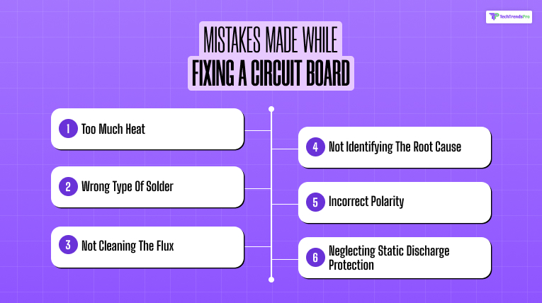
1. Too Much Heat
You can delaminate the copper and make the PCB unusable by overheating a pad or trace. Employ a temperature-controlled iron and short contact time.
2. Wrong Type Of Solder
Some soldering repairs don’t work because of incompatible solder (e.g., using leaded and lead-free solder together). Pick one and stick with it.
3. Not Cleaning The Flux
Flux residue is an electrically conductive material in the wet state and may result in shorts. Clean it off always after soldering.
4. Not Identifying The Root Cause
Replacement of spare parts without determining why the failure happened (e.g., shorted power rail or overvoltage) will result in repeat failures.
5. Incorrect Polarity
Diodes, capacitors, or ICs installed in reverse are a frequent mistake that can ruin parts.
6. Neglecting Static Discharge Protection
Sensitive ICs like microcontrollers or memory ICs may be destroyed by even small static charges. Use ESD mats and wrist straps.
Pro Tips For Successful PCB Repair
- Cover nearby components with Kapton tape to protect against heat.
- Label jumper wires clearly so future service will be less confusing.
- Solder initially on scrap boards when testing challenging repairs.
- Have on hand a component tester to test resistors, capacitors, and transistors.
Is It Worth Repairing A Circuit Board?
Yes — circuit boards can and should be repaired, particularly if the device is expensive or unique. From home electronics and appliances to business hardware and vintage equipment, PCB repairs can:
- Save money
- Cut e-waste
- Prolong product life
- Enhance your own technical capabilities. But on high-density multilayer PCBs, repairs may be worth only if done with professional tools, or simply won’t be worth it if the damage is too far inside internal layers.
With the appropriate tools, skills, and patience, you can bring new life to dead electronics and be your own electronics technician.
If you’re interested in exploring more about the world of PCB board repair, check out https://www.pcbasic.com/blog/pcb-board-repair.html for insightful articles and expert tips.
Happy repairing
Additional Resources: