
Using newly formed advanced technology has become bread and butter for us. At times we will need a medium that will be used to take the excessive load.
Hole technology was the one widely used for this purpose. However, this has changed with SMT and Smd which apparently are a lot more technologically advanced.
But, how to know the difference between the two?
Well, if ‘What Smt vs Smd’ is your query then you have reached the right place. In this excerpt below I will explain the two with an elaborate difference of SMT vs SMD. Additionally, in this article most of the questions regarding this subject will be answered.
What Is SMT?
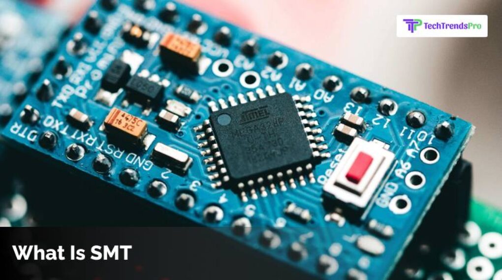
Surface Mount Technology a new design that is used to place the printed components on the circuit board. The earlier versions used to assemble the circuit referred to components on the board that were then inserted into the holes.
This method requires careful preparation to make sure that all cables used are using the correct technique and fit different plates. The design also requires a large circuit board that can accommodate multiple circuits.
However, with SMT, the assembly process is very efficient because the components there are soldered automatically to the board. Because this technique will not require routing the cables through the PCBs, then the assembly process becomes simpler, efficient, plus cost-effective.
The SMT also saves space as it mounts on both the sides, so that more components can be sprayed onto a small circuit board. This is a reason why modern devices are comparatively small despite having so many functions.
What Is SMT Process?
Surface mount technology is an electronic assembly area that is used to mount electronic components on the printed circuit board surface. However, we have learnt this before only.
So, before we finally learn SMT vs SMD, let me answer some of the most interesting queries on the subject of SMT.
(PCB) instead of inserting the components through holes which is the traditional assembly. SMT is designed to reduce manufacturing costs and use PCB space more efficiently.
Now with this introduction of SMD technology, it is possible to build complex electronic circuits in much smaller and smaller assemblies with a comparatively higher degree of automation.
What Is SMT Semiconductor?
For this you have to understand the difference between the semiconductor and the SMT.
Today’s conventional electronics and technological manufacturing will consist of the primary surface mount and semiconductor packaging technology processes. When the two are placed simultaneously they can make up the majority of generally accepted devices, from laptops, Pcs, Tablets and cell phones.
Even high-end smart toasters use these two kinds of technologies. The products resulting can also be used in cars, remote controls, televisions, and stereos. However, a lesser-known technology is also finding its mark in the markets: they are microelectronics.
What is the difference between conventional and SMT?
This is basically explaining the difference between SMT & through-hole components.
Through-hole components are mostly used for high-reliability products that will require much stronger between-layer connection.
While SMT components are solely joined to the board surface by soldering, the component connections with ‘through holes’ go through the board, making the components a lot more environmentally resistant.
What Is SMD?
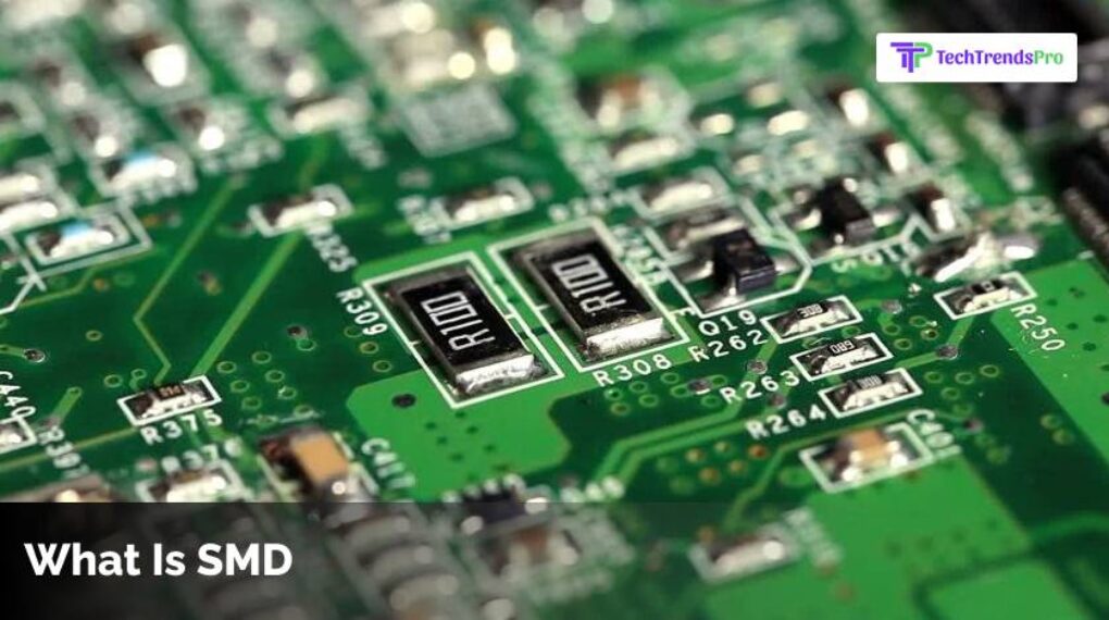
You need to understand this before you learn the difference between smd vs smt. This is known as the surface-mount device.
SMD is the electronic device on which the components can be mounted or placed on the surface directly of the circuit board.
Surface Mount Technology, or SMT for short, is the process that is used to make an SMD. In the electronic industry, this has largely replaced through-hole technology, in which components are fitted with wire conductors in the holes of the circuit board.
Both the technologies may be utilised on one board for non-surface mount components through large transformers and cooled down power semiconductors.
The SMT component is typically small as compared to its through-hole counterpart because there are smaller connections or no connections at all. It can also have short pins, and connectors of different types, a solder ball array (BGA), flat contacts, or connectors on the component’s body.
What Does SMD Stand For In Soldering?
Welding is a joining process which is used to join together different types of metals by welding fusion. Solder is known as the metal alloy which is usually made out of lead and tin, that is fused with a hot iron.
The iron then heats up to above 600 degrees Fahrenheit, which is then cooled to create the strong electrical connection.
How Do I Use Solder Paste In SMD?
With the right components you can do SMD soldering on your own. Therefore, before we finally learn smt vs smd, here is a step by step guide of doing the smoldering.
Soldering the resistor for CMD is one of the easiest way to begin learning SMD soldering.
Begin by applying the flux onto the circuit board’s pad. The flux then cleans the pad before facilitating the correct application of solder.
Apply some of the solder to the tip of the iron and then slowly touch the pad of the circuit board with the tip. This is so that solder goes into the pad.
Put the resistor in place and hold it with tweezers while touching the solder tip to heat up both components and the PCB pad.
Now, resistance should be attached on one side. Reapply the solder to the solder tip, and then touch the solder tip from the other side.
Your resistor will be ready by now to go, however you can still check the soldered joints with a magnifying glass or a microscope to ascertain that the connection has been done properly.
What Is The Difference Between SMT And SMD?
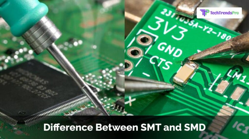
Now, we finally come to the difference between smt vs smd.
The major difference between the two is that,
SMD (surface mount device) basically means an electronic component which mounts on the printed PCB.
SMT (Surface Mount Technology), on the other hand, describes the process with which electronic components are placed on a circuit board.
What Is an SMD Capacitor?
Surface mount SMD or SMT capacitors are utilized in very high amount production. The number of equipment is more than billions. They are lead-free, small and can easily be attached to any modern printed PCB with automatic placing machines. Of these, SMD ceramic capacitors are widespread.
What Is SMD Resistor?
An SMD resistor is a kind of resistor which is designed for the surface mounting purpose. The SMD portion of the “SMD resistor” implies a surface mounted device. The SMD is an electronic component which could be mounted directly on the PCB with the help of the “Surface Mount Technology” (SMT).
Smt Vs Smd Fuse
SMD fuses are on-board network security: designed for an automatic mounting. SCHURTER fuse is something that offers a wide variety of solutions for the primary and secondary securement directly on to the circuit board. The UMT 250, UMTH, UMF 250, and fuses offer compact and accurate solutions which are also pulse proof.
What Are The Advantages Of SMT Surface Mount Technology Or SMD Surface Mount Devices?
Now that you have understood smt vs smd, it is easy to understand the advantages for the two.
Advantages For SMT
Self-correcting component placement – The surface tension of the weld forces the components to align with the weld pads. This reduces location errors.
Cost: SMDs or smaller components cost less than their larger through-hole versions.
Design Flexibility – You can combine SMT and through hole fabrication on the same circuit board for more functionality.
EMC Compatibility – Smaller deliveries with lead induction being lower, giving you a small radiation circuit area for the best electromagnetic compatibility.
Factory automation – By standardizing design and components, manufacturing can also be automated.
Faster production setup – No need to drill PCBs for assembly.
Higher Lap Speeds – Most manufacturers consider this their biggest benefit.
Lower resistance / induction – High frequency power reduces the unwanted consequences of the RF signals.
Manufacturing / Production Speed / Efficiency – Reduced / eliminated drilling into shorter setup duration, and increased manufacturing speed.
Multitasking: High-end components are versatile.
Quantity (and quality): Every component can be placed on each side of the PCB, creating connections for every component. Fewer PCB is required for the devices.
Selective welding: welding can be customized. The components are joined with a solder, which is also an adhesive.
Stability – Better power output is achieved through mechanical shock / vibration conditions. SMT connection is reliable.
Advantages For SMD
- The components are smaller.
- Component density is higher.
- Lower acquisition costs and preparation time for production.
- Easier and automated assembly, and much faster.
Final Thoughts
Hopefully we were able to understand the difference between smt vs smd and at the same time all the queries of the two.
If you have any other queries do let us know and we will try to research and bring you the best answers.
Read More: